FSK Application (fsk_app)
There are three variations of the FSK (Frequency Shift Keying) application that support the three different modes of operation. The three modes are transmit only, receive only, and both transmit and receive.
Description
Those who have some experience in digital communications are familiar with the basic concept of the frequency shift keying (FSK) scheme of modulation making it a practical use case as an example to become familiar with the OpenCPI framework. The basic principle is that a binary digit (‘0’ or ‘1’) may be transmitted as an RF signal by shifting the carrier frequency. For example, a +1000 Hz offset may be interpreted as the digit ‘1’ and a -1000 Hz offset as the digit ‘0’.
The FSK application can be used to transmit a file from one platform to another, but the application does not follow a conventional approach normally used for low probability of error and high throughput reception. It does not apply any error correction or standard layer 2 frame formatting. It does have a packet-builder component that applies a header and a tail sequence to allow the receiver to detect when the data starts and ends. It also has a component that uses a pattern detection component to detect the header and tail, which is used by the receiver processing path to pass the raw data payload to be written to a file.
The components that comprise the three applications are shown in Figure 5: Details regarding library location and specified property values may be observed by viewing the application directly. The names of each are abbreviated for simplicity in explaining functionality. Those components designed specifically to support this FSK application are found in the “examples” project component library. The other components can be found in the ‘ocpi.comp.sdr’ and ‘ocpi.core’ project component libraries.
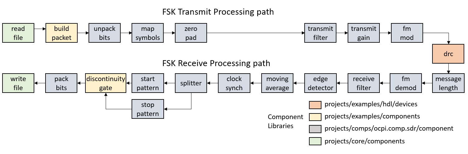
Figure 5: FSK application components.
The three versions of this application are:
apps/fsk_app_txrx.xml(Application that executes platform rf loopback)
apps/fsk_app_tx.xml(Application that executes platform transmit only)
apps/fsk_app_rx.xml(Application that executes platform receive only)
All three applications require the Digital Radio Controller (DRC) component. The TXRX version contains all components shown in Figure 5:. The TX version contains only those components identified as the FSK Transmit Processing Path and the RX version contains those components identified as the FSK Receive Processing Path.
Each execution mode is illustrated in Figure 6:
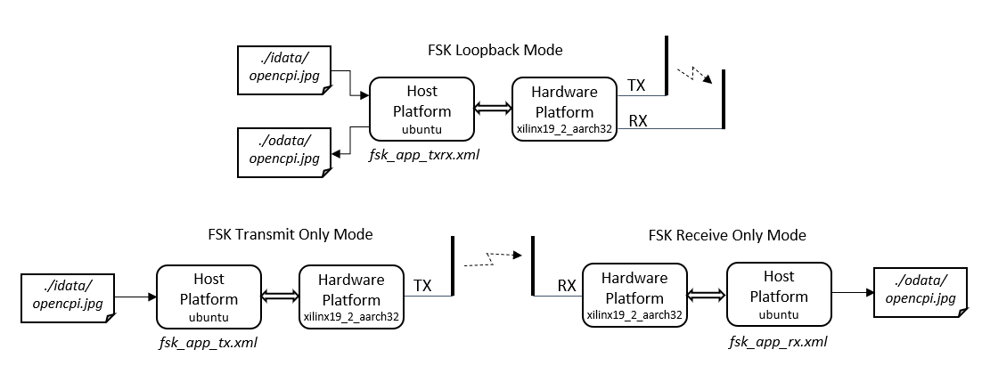
Figure 6: FSK application modes of execution.
Each application may be executed directly using the ‘ocpirun’ command with the user specifying desired component properties. They may also be executed using the OpenCPI Application Control Interface (ACI) application to use argument options to select desired properties. The ACI application is located at:
fsk_app/fsk_app.cc
When built for a specified host platform such ubuntu20_04, the executable would be located at:
fsk_app/target-ubuntu20_04/fsk_app
Please read the fsk_app README.md file found in then application’s directory for more details pertaining to execution method and option selection. The README.md also provides details for installation and building of all required OpenCPI elements. The README.md file is best observed when viewing the applications git repository directory.
Digital Radio Controller (DRC)
The DRC component drives the specific OpenCPI hardware platform. The DRC for this application may be set in transmit, receive, or transmit/receive modes. It is used to control the RF elements of the platform to include local carrier, sampling rate, gain for both transmit and receive paths. The DRC performs interpolation and decimation when necessary and applies carrier offset when specified.
Read File
The transmit path sends the data content of any user specified file. This component opens the file and outputs the file’s data content in byte format and passes to its output port.
Build Packet
This is a custom component developed to support the FSK application. It first applies a synchronization stream of 0x55 bytes used to stabilize the receiver when data is detected on its input port. The number of synchronization bytes should be scaled according to desired data rate. More bytes are required as the rate is increased. Header and Tail bytes are added to the data to allow the receiver to detect the start of the data stream and the end. When the Tail bytes are detected, the receiver closes the write file. The Data packet structure for sending a file using the FSK application is shown in Figure 7:

Figure 7: FSK application data packet frame.
Unpack Bits
Data is received on the input port as unsigned character samples in byte format. Each bit of the received sample is extracted and sent to the output port as a Boolean sample.
Map Symbols
Translates input binary samples to signed short integer samples.
Mark symbol (‘1’) = 32767
Space symbol (‘0’) = -32767
Zero Pad
Increases the number of samples per symbol by adding zeros.
Adds 9 additional samples for total 10 samples per symbol (SPS).
Transmit Filter
Applies Root Raised Cosine (RRC) tap coefficients to mitigate inter-symbol interference (ISI) and scales to normalize the output samples.
- RRC parameters:
Beta = 0.4
SPS = 10
Span = 6 symbols
Transmit Gain
The gain is used to set input amplitude used by the next component, the FM Modulator, to define frequency deviation between symbol marks. The applied gain value is 32767 to maximize amplitude.
FM Modulation
Generates a modulated baseband signal with positive or negative frequency around DC point based on input sample sign and amplitude shown in Figure 8:. The frequency deviation is maximized when amplitude is ± 2^15. The resulting frequency value is dependent on sample rate. At full scale, the frequency will be one half the sample rate. As rate increases, so does the signal bandwidth.
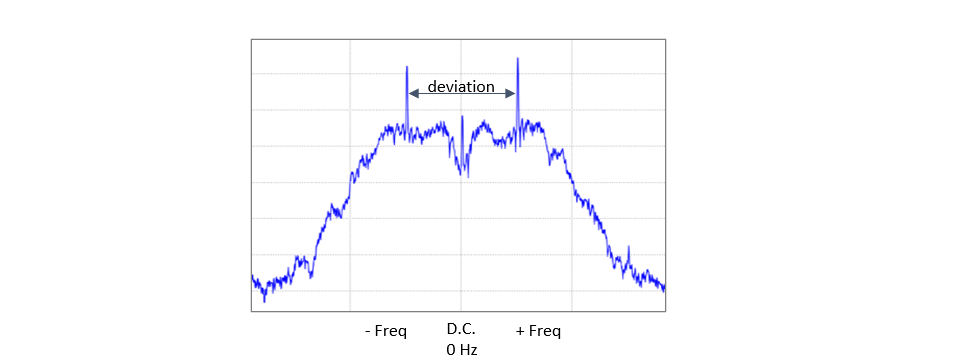
Figure 8: FSK baseband spectrum.
Message Length
The message length adjuster component is the first component of the receiver path following output samples from the receiver DRC. The samples out of the DRC have been processes by the rf front-end and downsampled to baseband. The message length adjuster is used on the receive path of the FSK application to mitigate flow of only single sample or low number of samples populating a port buffer which is impacted as the rate increases. It ensures the size of the propagated message so that each output buffer is full before sending to output port.
FM Demodulation
The FM demodulator component finds the angle between consecutive samples using the atan2 operation. The angle will be positive or negative dependent on the received baseband frequency.
Receive Filter
The receiver filter applies the matching RRC coefficients used by the transmit filter.
Edge Detector
The Edge detector uses a threshold value equal to 0 to detect the binary crossing point of the filtered samples. It generates a binary stream of samples. When the input port sample is greater than the threshold, the output sample is set to ‘1’. If the input sample value is less than or equal to the threshold, the output sample is set to ‘0’.
Moving Average
The moving average filter component is used to further smooth out the received symbols by averaging over a symbol period of 10 samples.
Clock Synchronization
The clock synchronization component is designed to detect the edges of oversampled binary input samples. The local clock is aligned with the symbol transition edge and will correct for minor variances in input sample rate. The component selects the 4th sample from the symbol edge of 10 symbol samples as the final received binary value to output.
Splitter
The splitter component is used to direct the data samples along two paths for header and tail detection.
Start Pattern
The pattern detection component passes all input samples to the output port but injects a discontinuity opcode into the stream when the “header” is detected. The output port is connected to the “open” port of the discontinuity gate component. The “header” bits are not passed to the output.
Stop Pattern
The pattern detection component passes all input samples to the output port but injects a discontinuity opcode into the stream when the packet “tail” is detected. The output port is connected to the “close” port of the discontinuity gate component. The “tail” bits are not passed to the output port.
Discontinuity Gate
The discontinuity gate component has two input ports and a single output port. The input ports are labeled ‘input_open’ and ‘input_close’. The component is used to pass only the data samples associated with the transmitted file arriving at the receiver in the FSK packet. Its initial state is the closed position allowing no samples out its output port. When a discontinuity opcode is received on the ‘input_open’ port, the component forwards all samples from the input port to the output port. If a discontinuity opcode is detected on the ‘input_close’ port, then the component stops passing samples from the ‘input_open’ port to the output port.
Pack Bits
This component takes the binary input samples and packages them into byte values and passes to the output port.
Write File
File write is a termination component that opens a destination file when the application is initialized. When byte data is received on its input port, the data is written to the open file
HDL Assembly workers
There are six assembly workers developed to support the FSK application. They were developed to support a case where most of the components are implemented as HDL workers and a case where most of the workers are implemented as RCC workers. In the mostly RCC case, HDL workers are still required to implement the DRC functionality to interface with the RF elements and configuration of the HDL platform. The mostly HDL case still requires the file read and write components for access to files on the host so some components must be implemented as RCC workers.
Figure 9: shows those components comprising the HDL assembly for the mostly HDL case. The figure shows the case for the transmit and receive (TXRX) mode. The TX only mode HDL assembly contains only the workers shown as the “Transmit Assembly Path” in the figure. The RX only mode HDL assembly contains only the workers shown as the “Receive Assembly Path” in the figure.
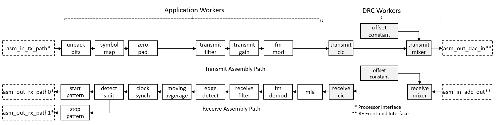
Figure 9: FSK HDL Assembly for mostly HDL workers.
Figure 10: shows those components comprising the HDL assembly for the mostly RCC case. The figure shows the case for the transmit and receive (TXRX) mode. The TX only mode HDL assembly contains only the workers shown as the “Transmit Assembly Path” in the figure. The RX only mode HDL assembly contains only the workers shown as the “Receive Assembly Path” in the figure. This assembly contains mainly those workers that implement the DRC.
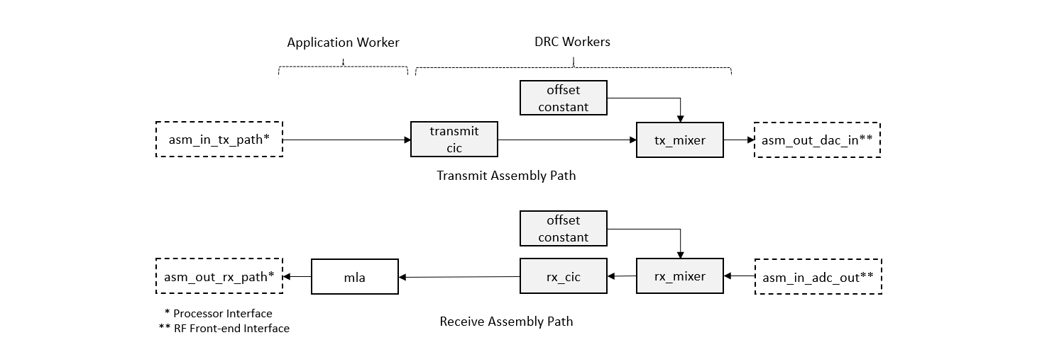
Figure 10: FSK HDL Assembly for mostly RCC workers.
All HDL assemblies for each FSK application mode and case are found at:
opencpi/projects/examples/hdl/assembly/fsk_app/
Hardware Portability
This application has been verified to execute on platforms:
e31x (Ettus E310)
plutosdr_csts (Analog Devices Pluto-ADALM)
zed (Divergent ZedBoard with FMCOMMS2 or FMCOMMS3 board)
zcu104 (AMD Zynq UltraScale+)
Execution
Follow the instructions provided in the README page of the repo for steps to build all required elements and execute the FSK application.
If using two platforms to transmit and receive a file, make sure that each carrier is tuned with the appropriate offset so that they align closely. The application does not provide carrier recovery. The exact carrier frequency is dependent of the stability of the platforms local oscillator which may vary by > 10kHz. The DRC parameter “offset_freq_mhz” may be used to fine tune either the transmit or receiver carrier. This could be done as trial and error. The most efficient approach is to employ a spectrum analyzer to view the carrier of each platform.