CIC Filter Worker - Decimation (cic_dec_csts)
CIC (Cascaded Integrator-Comb) filter combined with decimator.
Design
This device worker is the equivalent of cic_decimator_xs component within OpenCPI SDR Components Library (ocpi.comp.sdr).
CIC decimators are an efficient method of reducing the sample rate of an input signal by an integer factor. CIC decimators do not require any multiplication operations making them particularly suitable for compact FPGA designs.
In a CIC decimator the integrator stage is applied first, then the down sampling is applied before the comb stage is applied last. CIC filters have an inherent gain that typically needs to be removed; in this component this is done via a right shift operation allowing for power-of-2 gain compensation. A half-up rounding unit is used to minimise the amount of DC bias caused by the right shift operation.
A block diagram representation of the implementation is given in Figure 4:.

Figure 4: Block diagram of CIC decimator implementation.
Frequency Response
The frequency response of a CIC decimator is given by in (3).
In (3):
\(H[\omega]\) is the narrowband frequency response.
\(N\) is the order of the CIC filter (
cic_order)\(R\) is the down sampling factor (
down_sample_factor)\(M\) is the delay factor (
cic_delay, this must only be set to 1 or 2).
When down sampling a signal it is typically desirable to minimise the amplitude of any signals that will be above the Nyquist frequency of the lower sample rate as these signals will alias into the passband. The order and delay factor of the CIC sets the wideband frequency response of a CIC filter, with higher values giving more suppression of signals that will alias after the down sample operation.
The wideband frequency response (i.e. the response before the down sampling operation is performed) is shown in Figure 5: and Figure 6:.
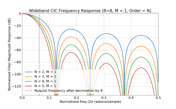
Figure 5: Wideband CIC frequency response. \(M = 1\). \(R = 8\).
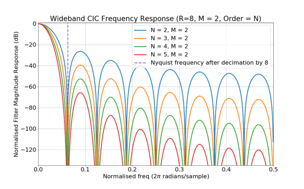
Figure 6: Wideband CIC frequency response. \(M = 2\). \(R = 8\).
Gain
Increasing the order and differential delay does not come for free; the larger they are the greater the gain of the CIC. A larger gain means the width of internal registers used by the CIC decimator (set by the parameter cic_reg_size) must be larger in order to store the calculated values. This in turn means the filter takes up more space on an FPGA.
The gain of a CIC decimator is given by \(G\) in (4)
The minimum cic_reg_size in bits needed to correctly perform the CIC decimation is given in (5). In this component inWidth is 16 bits.
Passband Attenuation
CIC decimators have attenuation in the passband. The larger the CIC order and delay factor the more attenuation in the passband. The narrowband frequency response of a CIC decimator is shown in Figure 7:.
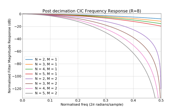
Figure 7: Narrowband (after decimation) CIC frequency response. \(R = 8\).
The narrowband frequency response of a CIC filter is same regardless of the down_sample_factor (\(R\)). This is shown in Figure 8:.
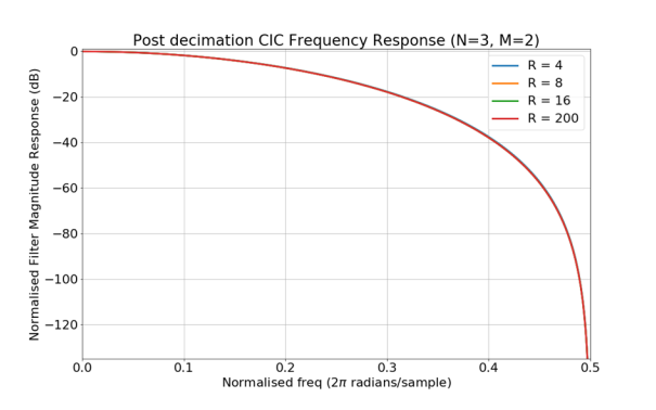
Figure 8: Narrowband (after decimation) CIC frequency response. \(N = 3\). \(M = 2\).
Mathematical Representation
(6) and (7) give a mathematical representation of the completed CIC filter implementation.
In (6) and (7), \(h[n]\) is the output values and \(x[n]\) is the input data stream.
In (7) the notation \(\binom{n}{x}\) is the binomial expansion, or more informally described as “\(n\) choose \(x\)”.
After the CIC filter implementation using the above, an attenuation stage is applied to allow the option of cancelling out the inherent CIC filter gain, this attenuation is implemented as a right shift, which is equivalent to the expression in (8).
In (8), \(y[n]\) is the final output of the component and \(S\) is the scale output property.
Interface
<componentspec>
  <property name="cic_order" type="uchar" writable="false" parameter="true" default="3" description="CIC order. Number of comb and integrator stages."/>
  <property name="cic_diff_delay" type="uchar" writable="false" parameter="true" default="2" description="Number of differential delay stages."/>
  <property name="cic_reg_size" type="uchar" writable="false" parameter="true" default="36" description="Internal data size used within the child primitives."/>
  <property name="down_sample_factor" type="ushort" writable="true" default="1" description="Down sampling factor."/>
  <property name="scale_output" type="uchar" writable="true" default="6" description="Output scale factor. CIC output is divided by :math:`2^{\texttt{scale_output}}`."/>
  <property name="flush_length" type="ushort" writable="true" default="0" description="Number of zero samples that should be inserted into the CIC on receipt of a flush opcode."/>
</componentspec>
Ports
Inputs:
input: Primary input samples port.Protocol:
complex_short_timed_sample-protOptional:
False
Outputs:
output: Primary output samples port.Protocol:
complex_short_timed_sample-protOptional:
False
Opcode Handling
Sample opcode messages are down sampled by the CIC decimator. The message boundaries of the input sample opcode message are preserved on the output sample opcode message. This means that output sample messages are smaller than the input sample messages by a factor of down_sample_factor. Input sample opcode messages where all the samples are discarded due to the CIC decimator are output as zero length messages.
As this component is designed to down sample the input data stream, when a timestamp opcode message is received there is a change the sample that the timestamp relates to may not be output from the component. For this reason the timestamp opcode messages are not directly passed through, but instead stored and incremented (by the sample interval) for each valid sample opcode message that is input. The corrected timestamp is then inserted into the output stream directly before the next valid output message with the sample opcode. The result of this is that timestamp opcode messages are passed through the component as close as possible to in position to the relative input stream position, and the timestamp is corrected so that it always contains the time of the next valid message with a sample opcode.
Sample interval opcode message are passed through the component from input to output. The sample interval is stored in the component so that it can be used to increment the timestamp.
Flush opcode messages trigger the component to insert flush_length zero samples into the input of the CIC in order to flush out any historical data. On receipt of a flush opcode message, backpressure is applied to the input port while the samples are flushed. This will typically result in the output of a sample opcode message that is roughly \(\frac{\texttt{flush_length}}{\texttt{down_sample_factor}}\) samples long. The flush opcode message is then passed from the input to the output.
All other opcodes are passed through the component unmodified and in the same position in the output stream as in the input stream.
Properties
cic_order: CIC order. Number of comb and integrator stages.Type:
ucharAccess:
Parameter:
TrueWritable:
FalseInitial:
FalseVolatile:
False
Default value:
3
cic_diff_delay: Number of differential delay stages. Must not be set to zero.Type:
ucharAccess:
Parameter:
TrueWritable:
FalseInitial:
FalseVolatile:
False
Default value:
2
cic_reg_size: Internal data size used within the child primitives.Type:
ucharAccess:
Parameter:
TrueWritable:
FalseInitial:
FalseVolatile:
False
Default value:
36
down_sample_factor: Down sampling factor. Must not be set to zero.Type:
ushortAccess:
Parameter:
FalseWritable:
TrueInitial:
FalseVolatile:
False
Default value:
1
scale_output: Output scale factor. CIC output is divided by \(2^{\texttt{scale_output}}\). Must not be set greater than \(\texttt{cic_reg_size} - 16\).Type:
ucharAccess:
Parameter:
FalseWritable:
TrueInitial:
FalseVolatile:
False
Default value:
6
flush_length: Number of zero samples that should be inserted into the CIC on receipt of a flush opcode.Type:
ushortAccess:
Parameter:
FalseWritable:
TrueInitial:
FalseVolatile:
False
Default value:
0
Implementations
cic_dec_csts(HDL)
CIC Compensation Filters
Passband attenuation is typically unwanted and can be compensated for by following the CIC decimator with an FIR filter. The frequency response of an idea compensation filter is shown in (9).
Wideband Compensation
The passband frequency response of CIC filter with a compensation filter across the entire passband is shown in Figure 9:.
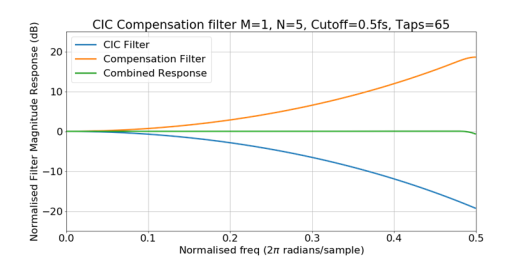
Figure 9: Narrowband frequency response of CIC with wideband compensation filter
Compensation across the entire passband is typically not recommended as it results in degraded rejection of aliasing signals compared to just a CIC decimator. This is shown in Figure 10:.
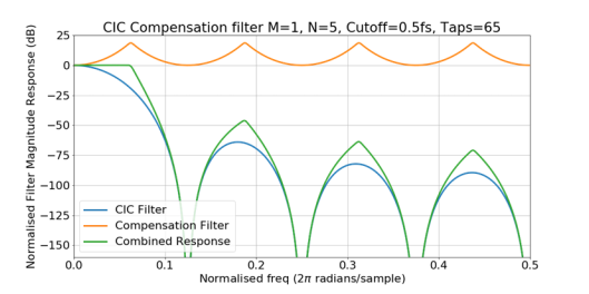
Figure 10: Wideband frequency response of CIC with wideband compensation filter
Narrowband Compensation
Narrowband compensation is when the CIC frequency response is only compensated for during part of the Nyquist bandwidth of the lower sample rate. Most systems use a narrowband compensation filter.
As a rule of thumb the cut-off frequency of the narrowband compensation filter should be \(F_{cutoff} \leq \frac{f_{s[low]}}{4M}\). If this condition is not met the performance of the CIC decimator, at some frequencies, will be negatively impacted by the compensation filter. This is shown in Figure 11: and Figure 12:.
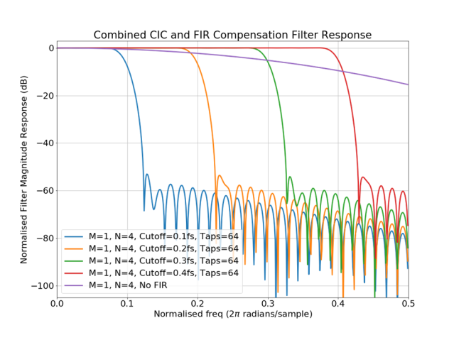
Figure 11: Narrowband Frequency Response of CIC with narrowband compensation filter
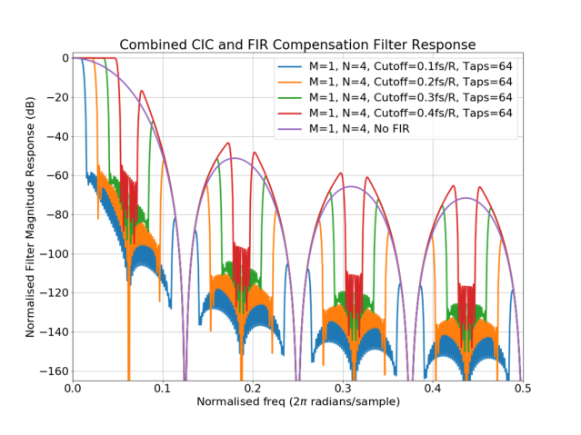
Figure 12: Wideband Frequency Response of CIC with narrowband compensation filter
Generating Filter Taps
The following python code can be used to generate the taps for an FIR compensation filter and to plot the system’s frequency response.
from scipy.signal import firwin2
from scipy.signal import freqz
import numpy as np
import matplotlib.pyplot as plt
np.seterr(divide='ignore', invalid='ignore');

# cutOff is the cut off freq as a fraction of the lower sample rate
# i.e 0.5 = Nyquist frequency
def getFIRCompensationFilter(R,M,N,cutOff,numTaps,calcRes=1024):
    w = np.arange(calcRes) * np.pi/(calcRes - 1)
    Hcomp = lambda w : ((M*R)**N)*(np.abs((np.sin(w/(2.*R))) /
                        (np.sin((w*M)/2.)) ) **N)
    cicCompResponse = np.array(list(map(Hcomp, w)))
    # Set DC response to 1 as it is calculated as 'nan' by Hcomp
    cicCompResponse[0] = 1
    # Set stopband response to 0
    cicCompResponse[int(calcRes*cutOff*2):] = 0
    normFreq = np.arange(calcRes) / (calcRes - 1)
    taps = firwin2(numTaps, normFreq, cicCompResponse)
    return taps

def plotFIRCompFilter(R,M,N,taps,wideband=False):
    if wideband: # Interpolate FIR filter to higher sample rate
        interp = np.zeros(len(taps)*R)
        interp[::R] = taps
        freqs,compResponse = freqz(interp)
        w = np.arange(len(freqs)) * np.pi/len(freqs) * R
    else:
        freqs,compResponse = freqz(taps)
        w = np.arange(len(freqs)) * np.pi/len(freqs)
    Hcic = lambda w : (1/((M*R)**N))*np.abs( (np.sin((w*M)/2.)) / (np.sin(w/(2.*R))) )**N
    cicMagResponse = np.array(list(map(Hcic, w)))
    combinedResponse = cicMagResponse * compResponse
    plt.plot(freqs/(2*np.pi),20*np.log10(abs(cicMagResponse)), label="CIC Filter")
    plt.plot(freqs/(2*np.pi),20*np.log10(abs(compResponse)), label="Compensation Filter")
    plt.plot(freqs/(2*np.pi),20*np.log10(abs(combinedResponse)), label="Combined Response")
    plt.grid(); plt.legend();
    axes = plt.gca(); axes.set_ylim([-200,25])
    plt.show()
Dependencies
The dependencies to other elements in OpenCPI are:
There is also a dependency on:
ieee.std_logic_1164
ieee.numeric_std
ieee.math_real
Limitations
Limitations of cic_decimator_xs are:
After a timestamp opcode message is received any zero length messages with the sample opcode are discarded until the next valid message with a sample opcode is received. Under all other conditions zero length sample opcode messages are passed directly through.
Testing
Tested platforms: None
Component testing not completed.