complex_mixer HDL Worker
Application worker HDL implementation with settable runtime configuration parameters and a numerically-controlled oscillator (NCO) that uses the coordinate rotation digital computer (CORDIC) algorithm to generate the digital sine wave for the complex multiply operation.
Detail
The following figure shows a functional representation of the HDL implementation:
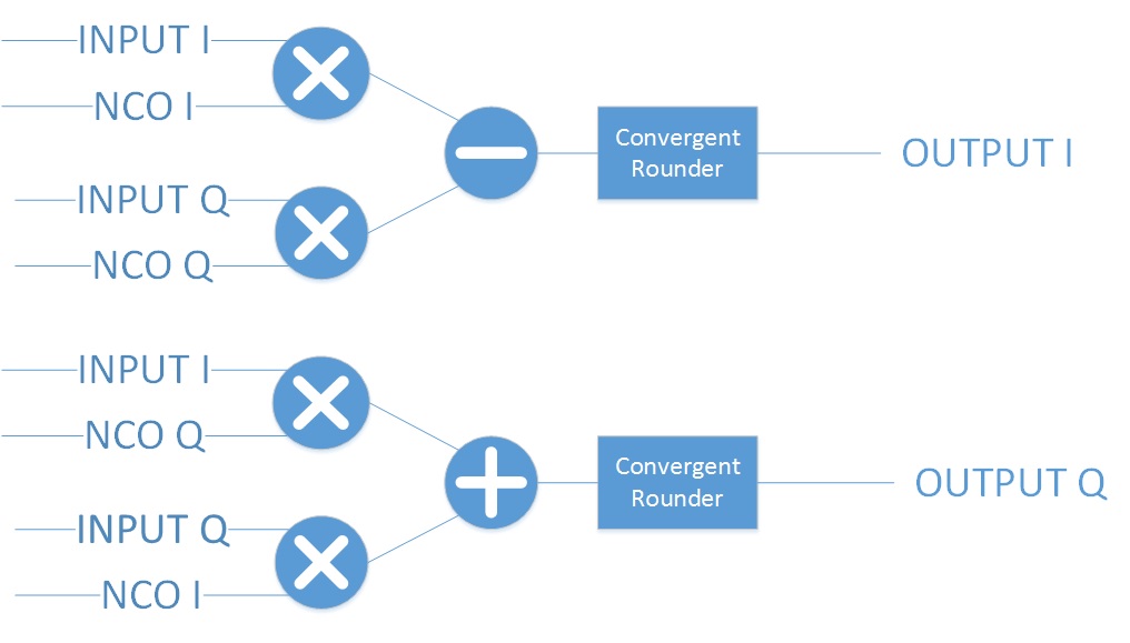
Figure 2: Complex Mixer Functional Diagram
Build-time parameters can be used to control the width of the NCO data output (NCO_DATA_WIDTH_p),
the width of the input data (INPUT_DATA_WIDTH_p), the number of stages in the
Coordinate Rotation Digital Computer (CORDIC) used to implement the NCO (CORDIC_STAGES_p)
and the amplitude of the NCO’s sine wave (mag).
There are also parameters to control insertion of a peak detection circuit (PEAK_MONITOR_p)
a Chipscope circuit (CHIPSCOPE_p, and a Vivado integrated logic analyzer (VIVADO_ILA_p).
The peak detector has two inputs and does not compute magnitude. The output of the
the peak detector (peak) is either the peak of I or the peak of Q, whichever is greater.
The enable input is available to either enable (true) or bypass (false) the circuit.
In bypass mode, the HDL worker does not use pipe-lining registers. It uses FPGA multipliers to
process input data at the full clock rate. The HDL worker produces valid output
two clock cycles after each valid input.
The relationship between the frequency shift magnitude and the NCO output frequency is given by the following equation:
In this equation:
phs_inc is the NCO phase increment, which is runtime-configurable and has a data type of 16-bit signed short.
phs_acc_width is fixed at 16.
The input clock frequency is the sample rate of the samples.
A positive and negative phs_inc will mix up and down, respectively. Use the following equation as an aid in setting phs_inc to have the desired mixing effect:
The following figure shows a block diagram representation of the HDL implementation:
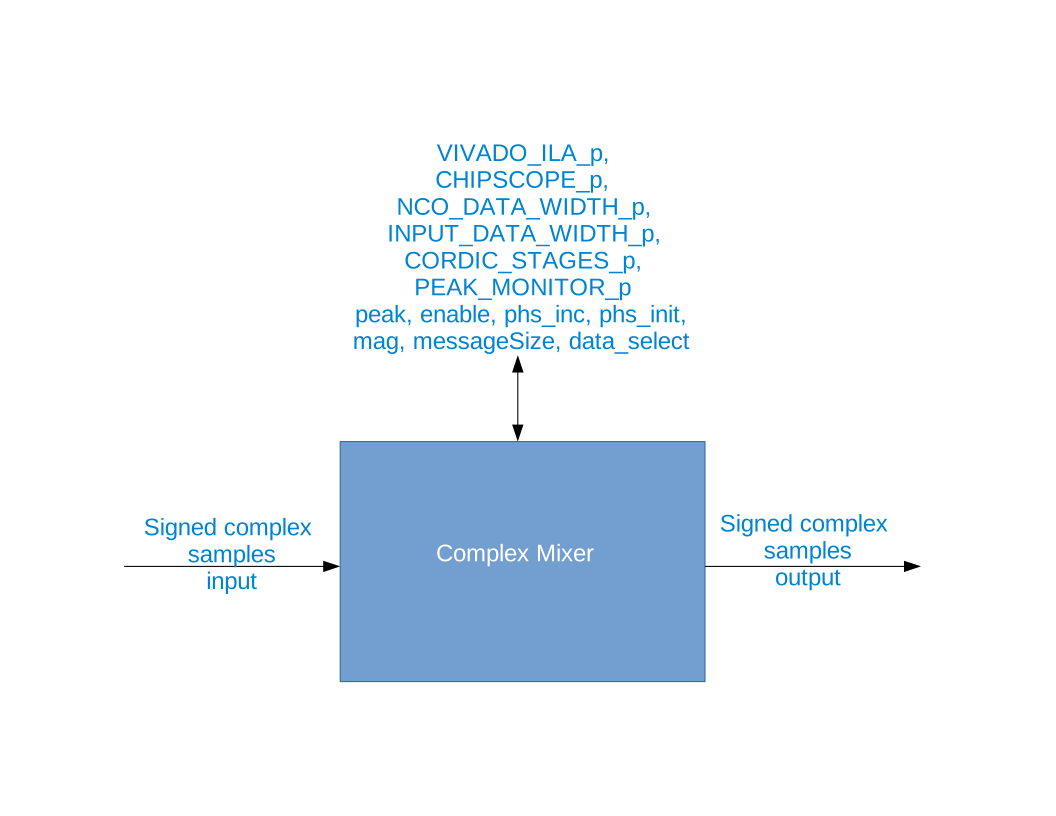
Figure 3: Complex Mixer Block Diagram
Worker Properties
VIVADO_ILA_pType:
boolAccess:
Parameter:
TrueWritable:
FalseInitial:
FalseVolatile:
FalseRead back:
False
Default value:
false
CHIPSCOPE_pType:
boolAccess:
Parameter:
TrueWritable:
FalseInitial:
FalseVolatile:
FalseRead back:
False
Default value:
false
NCO_DATA_WIDTH_pType:
ucharAccess:
Parameter:
TrueWritable:
FalseInitial:
FalseVolatile:
FalseRead back:
False
Default value:
12
INPUT_DATA_WIDTH_pType:
ucharAccess:
Parameter:
TrueWritable:
FalseInitial:
FalseVolatile:
FalseRead back:
False
Default value:
12
CORDIC_STAGES_pType:
ucharAccess:
Parameter:
TrueWritable:
FalseInitial:
FalseVolatile:
FalseRead back:
False
Default value:
16
PEAK_MONITOR_pType:
boolAccess:
Parameter:
TrueWritable:
FalseInitial:
FalseVolatile:
FalseRead back:
False
Default value:
true
peak: Peak detector output. Either peak of I or peak of Q, whichever is greater.Type:
shortAccess:
Parameter:
FalseWritable:
FalseInitial:
FalseVolatile:
TrueRead back:
False
Default value:
None
phs_initType:
ushortAccess:
Parameter:
FalseWritable:
TrueInitial:
FalseVolatile:
FalseRead back:
False
Default value:
0
mag: Must be in the range \(-2^{(NCO\_DATA\_WIDTH\_p-1)} <= mag <= 2^{(NCO\_DATA\_WIDTH\_p-1)}-1\) for the worker to operate properly.Type:
ushortAccess:
Parameter:
FalseWritable:
TrueInitial:
FalseVolatile:
FalseRead back:
False
Default value:
1024
messageSizeType:
ushortAccess:
Parameter:
FalseWritable:
TrueInitial:
FalseVolatile:
FalseRead back:
False
Default value:
8192
data_select: 0 = input data, 1 = output of NCO.Type:
boolAccess:
Parameter:
FalseWritable:
TrueInitial:
FalseVolatile:
FalseRead back:
False
Default value:
false
Worker Ports
in: Signed complex samples.Type:
streaminterfaceData width:
32Protocol:
iqstream_protocol.xmlZero length messages:
trueOptional:
False
out: Signed complex samples.Type:
streaminterfaceData width:
32Protocol:
iqstream_protocol.xmlZero length messages:
trueOptional:
False
Inputs:
Outputs:
Finite State Machine
This worker implements only one finite state machine (FSM). The FSM supports zero-length messages.
In future releases, this FSM will be replaced with a register delay-based mechanism currently used
in the dc_offset_filter HDL implementation. The following figure illustrates this FSM:
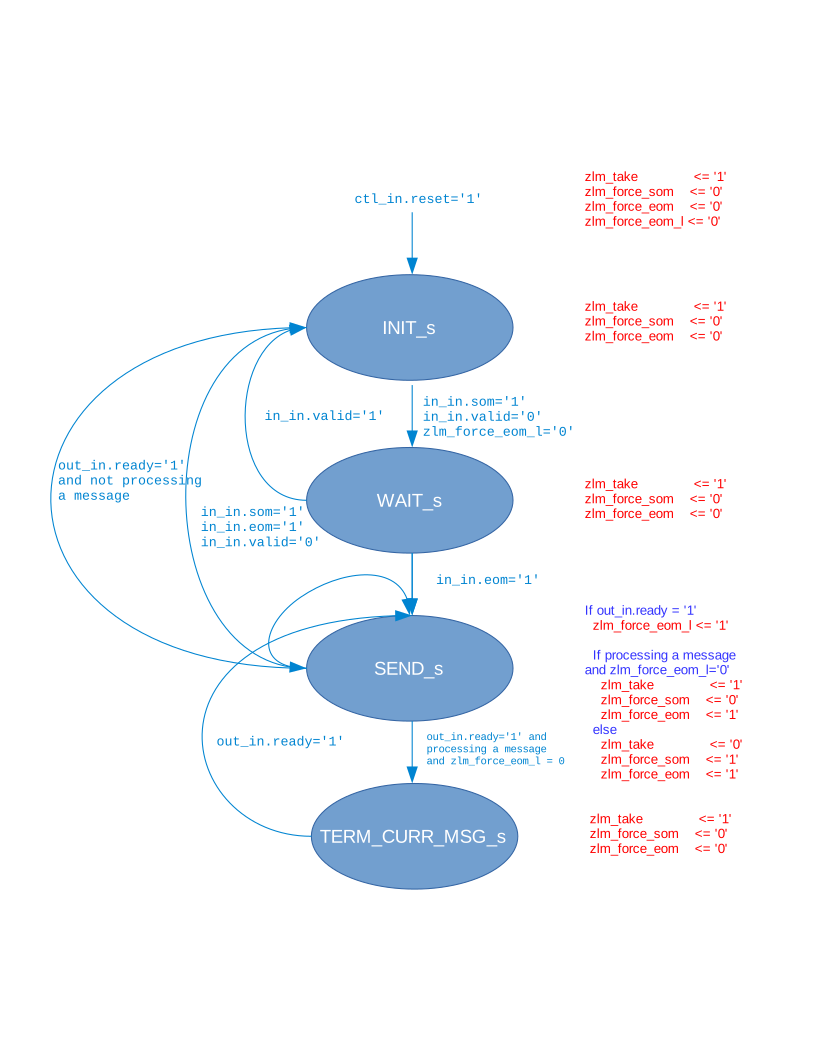
Figure 4: Complex Mixer Finite State Machine
Control Timing and Signals
The complex mixer HDL worker uses the clock from the control plane and standard control plane signals.
There is a startup delay for this worker: once the input is ready and valid and the output is ready,
there is a delay of CORDIC_STAGES_p+3 before the first sample is taken. After the initial delay,
valid output data is given two clock cycles after input data is taken (latency=2).
Utilization
Utilization reporting is not currently implemented.