x310 Getting Started Guide
This platform can be used to run OpenCPI applications on the Ettus USRP X310 hardware.
The Ettus Research USRP X310 is a high-performance, scalable software defined radio (SDR) platform
for designing and deploying next generation wireless communications systems. The hardware architecture
combines two extended-bandwidth daughterboard slots covering DC to 6 GHz with up to 160 MHz of baseband bandwidth.
The Ettus USRP X310 supports a range of plugin daughterboards that contain the baseband to
RF frequency modulation, PA and LNA functionality. This platform supports the UBX160 daughterboard only.
The x310 platform can be configured to operate with one or two 10Gbps ethernet interfaces, and one or two UBX160 daughter boards.
A calibration application is provided that can be used to perform I/Q balancing and DC offset correction. This application produces frequency dependent correction parameters for both UBX160 daughter cards.
The Ettus USRP X310 Getting Started Guide can be found in the X310 Getting Started Guide
The Ettus USRP X310 manual can be found here USRP Hardware Driver and USRP Manual
The Getting Started Guide for the OpenCPI DGRDMA reference platform, zed_ether contains similar
information to this Getting Started Guide.
Revision History
Revision |
Description of Change |
Date |
|---|---|---|
v1.0 |
Initial Release |
date |
Software Prerequisites
A Linux host PC with a Vivado 2019.2 installation (Lab Edition at a minimum to
run applications, Design Edition or Webpack to build a bitstream) and an
OpenCPI installation (Version 2.4 or later).
The Ethernet interfaces use raw sockets to communicate with the device, which
requires the CAP_NET_RAW capability. This can be accomplished either by running
as root, or (preferably) by setting this capability on the application executable.
For example, to work through the rest of this guide, run
$ sudo setcap CAP_NET_RAW+eip $(readlink -f $(which ocpihdl))
$ sudo setcap CAP_NET_RAW+eip $(readlink -f $(which ocpirun))
to enable raw sockets for ocpihdl and ocpirun. Note that to use an ACI
application rather than ocpirun, the capability needs to be set on the
application binary as part of the installation process. If you want to debug
an application, the gdb and bash executables also need the capability.
$ sudo setcap CAP_NET_RAW+eip $(readlink -f $(which gdb))
$ sudo setcap CAP_NET_RAW+eip $(readlink -f $(which bash))
$ gdb --args ocpirun -d -l 8 <application>.xml
Hardware Prerequisites
The OpenCPI x310 platform has been tested using
Ettus USRP X310 fitted with one or two UBX160 daughter boards
National Instruments 783345-01 10 Gigabit Ethernet Card (PCIe)
2 x 10 Gigabit Ethernet Cable w/SFP+ Terminations
The USRP X310 provides three interface options – 1 Gigabit Ethernet (1 GigE), 10 Gigabit Ethernet (10 GigE), and PCI-Express (PCIe). Using this OpenCPI platform requires use of either one or both 10 GigE interfaces.

A more detailed description of the x310 ethernet connection using the SFP+ connectors can be found in the X310 Interfaces and Connectivity
Platform details
This platform provides one dataplane transport called ether, which can be
used to connect input and output ports in the container XML file.
The x310 platform has several configurations. These are defined in files platforms/x310/cfg_xxx.xml.
All configurations support DGRDMA operation. Configurations are defined for dual and single ethernet
interface usage, dual and single UBX-160 support, and for UDP usage via the ethernet interfaces.
Note that the dual UBX-160 configuration can be used with applications that require only a single
UBX-160 daughter board.
Platform Configuration |
Transport |
Daughter Board |
Usage |
|---|---|---|---|
cfg_base_single_eth.xml |
single ethernet |
none |
Configuration with no x310 hardware (ADC, DAC, UBX-160) support. Used during OpenCPI platform and DGRDMA development |
cfg_base_dual_eth.xml |
dual ethernet |
none |
Configuration with no x310 hardware (ADC, DAC, UBX-160) support. Used during OpenCPI platform and DGRDMA development |
cfg_base_single_udp.xml |
UDP |
none |
Configuration with no x310 hardware (ADC, DAC, UBX-160) support. Used during OpenCPI platform and UDP development. Designed for use with a 64 bit wide SDP bus. |
cfg_base_single_udp8.xml |
UDP |
none |
Configuration with no x310 hardware (ADC, DAC, UBX-160) support. Used during OpenCPI platform and UDP development. Designed for use with a 32 bit wide SDP bus. |
cfg_single_ubx_160.xml |
dual ethernet |
single |
Dual Ethernet / single UBX-160 can be used if one UBX-160 daughter board is present. Uses fewer FGPA resources than dual UBX-160 configuration |
cfg_dual_ubx_160.xml |
dual ethernet |
dual |
Dual Ethernet / dual UBX-160 used by calibration assembly and loopback example application |
cfg_single_ubx_160_single_eth.xml |
single ethernet |
single |
Single Ethernet / single UBX-160 version. Uses fewer resources than the dual Ethernet version |
cfg_dual_ubx_160_single_eth.xml |
single ethernet |
dual |
Single Ethernet / dual UBX-160 version. Uses fewer resources than the dual Ethernet version |
If dual ethernet is required then dual_ethernet must be set to true in the configuration XML
(as is done in the relevant configurations above).
Example Assemblies / Containers
The X310 platform has a number of example assemblies. These are located in directory x310/hdl/assemblies.
Assembly |
Container |
Configuration |
Usage |
|---|---|---|---|
calibration_assy.xml |
cnt_dual_ubx_160 |
cfg_dual_ubx_160 |
UBX-160 calibration |
lookback_assy.xml |
cnt_dual_ubx_160 |
cfg_dual_ubx_160 |
Simple test application |
smoketest_assy.xml |
cnt_base_single_eth |
cfg_base_single_eth |
Used during OpenCPI platform and DGRDMA development |
smoketest_assy.xml |
cnt_base_dual_eth |
cfg_base_dual_eth |
Used during OpenCPI platform and DGRDMA development |
udp_assy.xml |
cnt_base_single_udp |
cfg_base_single_udp |
Example bitstream with same workers as smoketest_assy.xml but including UDP support. See Using the x310 Platform with UDP transport |
Setup Guide
In order to set up a host system to run applications on this platform, the following steps need to be completed:
Build the example bitstreams
Connect the host PC to x310 hardware
Set up the JTAG cable drivers
Load a bitstream onto the FPGA using Vivado
Modify the setup-runtime.sh script
Modify the system.xml file specifying the system configuration
Load a bitsream onto the FPGA using
ocpihdl
Build the example bitstreams
Install the platform by running
$ ocpiadmin install platform x310 --package-id ocpi.osp.x310 --minimal
See the ocpiadmin(1) man page for command usage details.
To build the assemblies and other components used in the rest of this guide, go to the x310 directory and run
$ ocpidev build project --hdl-platform x310 --workers-as-needed
Connect the host PC to the x310 hardware
If using a single Ethernet connection, connect the PC (network interface card) to the x310 (Rear Panel 1G/10G ETH Port 0).
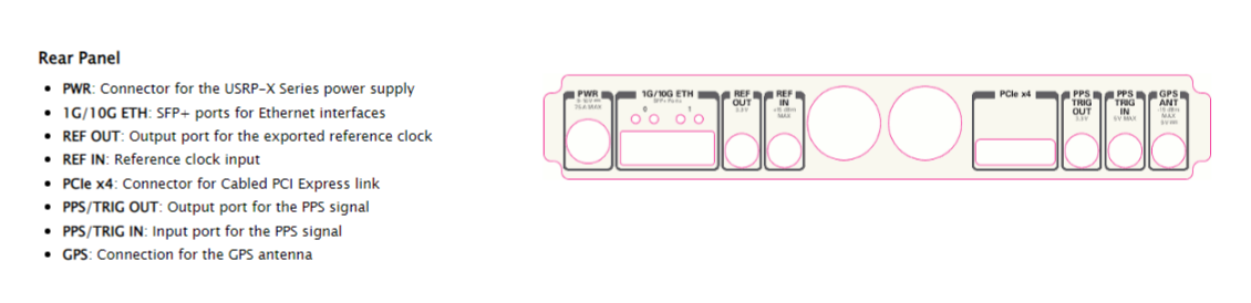
If using two Ethernet interfaces, connect the two PC (network interface card) interfaces to the x310 Rear Panel 1G/10G Ports 0 and 1. The OpenCPI DGRDMA functionality requires both ethernet interfaces to be bonded together to form a single aggregated link. Packets sent between the x310 hardware and the PC are then able to use both physical ethernet interfaces. Treating them as a single link.
Create a Linux bonded interface as follows. Note that this will need repeating after a reboot.
Run the following commands as root to create a Linux bonded interface (assuming the
two interfaces on the PC are named eth1 and eth2):
$ ip link add bond0 type bond
$ echo balance-rr > /sys/class/net/bond0/bonding/mode
$ echo 100 > /sys/class/net/bond0/bonding/miimon
$ ip link set eth1 down
$ ip link set eth2 down
$ ip link set eth1 master bond0
$ ip link set eth2 master bond0
$ ip link set bond0 up
This creates a bonded network interface called bond0 using the balance-rr
method (which uses a round-robin algorithm to dispatch outbound packets on the
two interfaces). The bonded interface name and MAC address should be used for all
OpenCPI configuration as described below (usually the MAC address of the first
physical interface added is used, eth1 in this case).
If you wish to use an interface MTU larger than the default of 1500 bytes, it must be configured on the network interface.
To verify that networking is properly configured, manually load the example OpenCPI bitstream (built in Build the example bitstreams) into the device using Vivado Hardware Manager (see Loading a bitstream into the x310 FPGA Using Vivado). Verify that the network interface is up and visible to OpenCPI:
$ ocpihdl ethers
 1. lo: MAC address none, up, connected, loopback, IP address: 127.0.0.1
 2. ens36: MAC address 00:0c:29:e2:30:24, up, connected
Then perform discovery:
$ export OCPI_ENABLE_HDL_NETWORK_DISCOVERY=1
$ ocpihdl search
OpenCPI HDL device found: 'Ether:ens36/80:1f:12:7c:d7:fa': bitstream date Thu Mar  3 08:08:11 2022, platform "zed_ether", part "xc7z020", UUID 1fbbe888-9b0c-11ec-a9eb-dbc5900fab1a
This requires raw socket access: either run as root or set the CAP_NET_RAW
capability on the ocpihdl executable as described in Software Prerequisites.
The OCPI_ENABLE_HDL_NETWORK_DISCOVERY environment variable must be set to
search for Ethernet devices as shown above. The OCPI_SYSTEM_CONFIG environment
variable must not be set.
If no devices were found, refer to Troubleshooting section.
Set up the JTAG cable drivers
Ensure that the cable drivers are installed - once Vivado is installed, a separate script needs to be run to install drivers on Linux:
$ cd <xilinx install path>/Xilinx/Vivado_Lab/2019.2/data/xicom/cable_drivers/lin64/install_script/install_drivers
$ ./install_drivers.sh
for Lab Edition, or
$ cd <xilinx install path>/Xilinx/Vivado/2019.2/data/xicom/cable_drivers/lin64/install_script/install_drivers
$ ./install_drivers.sh
for Design Edition. Then change to the platform directory, and run:
$ cd x310/hdl/platforms/x310
$ ./jtagSupport_x310 cables temp
localhost:3121/xilinx_tcf/Digilent/25163522A3F0A=25163522A3F0A~
The text between the = and the ~ is the ESN (cable serial number),
25163522A3F0A in this example, which is used for writing the system.xml
file below. If this does not work, ensure that the cable drivers are installed
and that the USB cable is connected to the X310.
Loading a bitstream into the x310 FPGA Using Vivado
The x310 FPGA is programmed with a bitstream using the USB-JTAG interface (USB-B). Connect the Front Panel JTAG / USB connector to the PC.
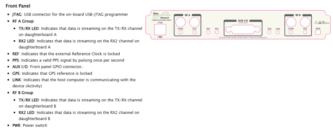
Programming is performed by instructing Vivado to execute a .tcl script in batch mode.
$ Xilinx/Vivado_Lab/2019.2/bin/vivado_lab -mode batch -source program_fpga.tcl
The .tcl script uses the hardware mananger to connect to the FPGA hardware and to program the FPGA.
Replace <bistream-name> below with the path to the bitstream to program.
open_hw_manager
connect_hw_server -allow_non_jtag
open_hw_target
current_hw_device [get_hw_devices xc7k410t_0]
refresh_hw_device -update_hw_probes false [lindex [get_hw_devices xc7k410t_0] 0]
set_property PROBES.FILE {} [get_hw_devices xc7k410t_0]
set_property FULL_PROBES.FILE {} [get_hw_devices xc7k410t_0]
set_property PROGRAM.FILE {<bitstream-name>.bit} [get_hw_devices xc7k410t_0]
program_hw_devices [get_hw_devices xc7k410t_0]
refresh_hw_device [lindex [get_hw_devices xc7k410t_0] 0]
close_hw_target
disconnect_hw_server
Modify the setup-runtime.sh script
The script (x310/applications/setup-runtime.sh), which needs to be sourced prior to running ocpirun or
an ACI application, needs to be modified to set the OCPI_ETHER_INTERFACE environment variable
to the name of the local ethernet interface that OpenCPI will use.
export OCPI_LIBRARY_PATH=/opencpi/projects/assets/artifacts:/opencpi/projects/core/artifacts:/work/x310/exports/artifacts:/opencpi/projects/tutorial/artifacts
export OCPI_SYSTEM_CONFIG=/work/x310/applications/system.xml
export OCPI_ENABLE_HDL_NETWORK_DISCOVERY=1
export OCPI_ETHER_INTERFACE=eth0
If dual ethernet operation is being used OCPI_ETHER_INTERFACE will need to be set to bond0.
Modify the system.xml file specifying the system configuration
The x310/applications/ directory contains the system.xml file used with the example applications. You will need
to modify it as described below.
<opencpi>
   <container>
      <rcc load="1"/>
      <hdl load='1' discovery="static">
         <device name="Ether:enp4s0f0/00:50:c2:85:3f:ff" device="xc7k410t" platform="x310" esn="2516350FA123A" static="true">
         <instance worker='dgrdma_config_dev'>
            <property name="remote_mac_addr_d" value="0xa0369f6abf08"/>
         </instance>
         </device>
      </hdl>
   </container>

   <transfer smbsize="10M">
      <datagram2-ether load="1"/>
   </transfer>
</opencpi>
The <device> tag should have the following attributes:
nameshould beEther:<interface name on PC>/<MAC address of FPGA>. Please note that:The interface name on the PC can be found by running
ip link. If using a dual ethernet configuration, the bonded ethernet name on the PC should be used (e.g. “Ether:bond0/…”)The MAC address can be found using
ocpihdl searchas described in Connect the host PC to the x310 hardware. It should be written as pairs of characters separated by colons.
deviceshould bexc7k410tfor the X310 platform.platformshould bex310for the X310 platform.esnshould be the value found in above in Set up the JTAG cable drivers.staticshould betrue.
The <instance> element should have the following tags:
A property tag with attributes defining the PC’s MAC address,
remote_mac_addr_d. This can be found by runningip addrand reading the MAC address for the local interface. This should be written as a hex number prefixed with0xIf dual ethernet is used, a tag specifying this, in the form
<property name="dual_ethernet_d" value="1" />
The following optional configurable parameters can be set as <property> elements of the <instance> element:
interface_mtu: MTU used by the FPGA. This is independent of the MTU used by the PC and should be set to the actual MTU of the Ethernet hardware for best performance [default: 1500 bytes]ack_wait: How long the FPGA waits before sending an ACK if there is no outgoing traffic [default: 187500 = 0.88ms @ 214MHz]max_acks_outstanding: Maximum number of ACKs accumulated in the FPGA if there is no outgoing traffic [default: 32 packets]coalesce_wait: How long the FPGA waits before sending a partially-empty frame (should be <= ack_wait). Set to zero to disable message coalescence [default: 125000 = 0.58ms @ 214MHz]dual_ethernet: set to 1 to enable second Ethernet interface, or 0 otherwise [default: 0]remote_dst_id: [default: 1]local_src_id: [default: 1]
Wait parameters are clock cycles at the OpenCPI application clock rate, which is 214MHz for this platform.
To use the old driver instead, replace the line
<datagram2-ether load='1'/>
with
<datagram-datagram_ether load='1'/>
Loading a bitstream via ocpihdl load (optional)
Once you have a system.xml file which specifies the JTAG cable ESN, you can
use ocpihdl load to load a bitstream into the FPGA. This is not required to
run an applicaton (ocpirun or an ACI application will automatically load the
FPGA bitstream is required), but may be useful to test the JTAG connection and to
do other low-level programming via ocpihdl.
$ ocpihdl load -d Ether:bond0/80:1f:12:7c:79:04 /path/to/artifact.bitz
Running an Application
Ensure that you have a valid system.xml file. Ensure that the following environment
variables are set:
Name |
Value |
Remarks |
|---|---|---|
|
1 |
Required to find network devices |
|
name of local Ethernet interface |
Used by transfer driver |
|
MTU for packets sent by the PC |
Optional; if not present, the default (1498) will be used. This must not be set larger than the actual MTU configured in the Linux network interface. |
|
Path to |
Required by OpenCPI framework |
|
Colon-separated list of artifact paths |
Required by OpenCPI framework |
Now you can run the loopback application:
$ cd x310/applications/loopback
$ python3 mkinput.py
$ ocpirun -d -l 7 loopback.xml
The loopback application comprises
File Reader, reads baseband samples from Test_file_in.dat at 2Msps. Test_file_in.dat is generated by the
mkinput.pyscript.mkinput.pytakes optional arguments. Thedecimation_factorargument should match theup_sample_factorof the CIC interpolator. The default values of each match.Interpolator (
ocpi.comp.sdr.dsp.cic_interpolator_xs) hdl worker used to increase the sample rate to 200 MspsDigitial-Radio-Controller (modulates the baseband signal to a carrier frequency of 2400 GHz)
Decimator (
ocpi.comp.sdr.dsp.cic_decimator_xs) hdl worker used to reduce the received baseband samples down from 200 MspsFile Writer, write receive samples to file Test_file_out.dat at 2 Msps
At the time of writing using log level 8 (-l 8) with a dual UBX160 configuration sends a large
amount of data to stdout due to the operation of the OpenCPI deployment planning algorithm. This
is liable to hang the system. Use of log level 7 (-l 7 as above) is recommended.
Troubleshooting
Refer to the Troubleshooting section of the zed_ether OSP (the OpenCPI DGRDMA reference platform).
Using the x310 Platform with UDP transport
OpenCPI contains support for using DGRDMA with a UDP transport. By default DGRDMA packets are carried using raw Ethernet, with the Ether Type field in the transport MAC layer being used to identify Control-Plane and Data-Plane packets.
When using UDP the same physical ethernet interface is used. However, at present dual ethernet operation is not supported. Only packets sent to the x310 hardware with Ether-Type IP (0x0800) and ARP (0x0806) are processed. Packets with other Ether-Types values are ignored. The UDP Port number is used to distinguish between Control-Plane and Data-Plane packets. Packets sent to other UDP ports will be ignored by the x310 hardware.
The ethernet / UDP components used in the FPGA filter received packets based on destination MAC address, IP destination address and destination UDP port.
- Packets with the following MAC destination addresses will be processed:
Destination MAC = LOCAL_MAC_ADDR
Destination MAC = Broadcast MAC (0xffffffffffff)
Destination MAC in multicast address group (01-00-5E-00-00-00 through 01-00-5E-7F-FF-FF)
- Packets with the following IP destination addresses will be processed:
Destination IP Address = LOCAL_IP_ADDR
Destination IP Address = multicast group (224.0.0.0 to 224.255.255.255)
Note the FPGA components do not “join” a multicast group. Care has to be taken in the network as the FPGA will process packets sent to the multicast Destination MAC / multicast IP Address / UDP Port = 18077 if these packets are present of the ethernet link connected to the x310.
By default the x310 platform uses the following port numbers:
Port Number |
Remarks |
|---|---|
18077 |
Control Plane UDP Port (destination UDP port of packets sent to the x310 hardware) |
18078 |
Data Plane UDP Port (destination UDP port of Data-Plane packets sent to the x310 hardware) |
The PC’s network interface used for communicating with the x310 needs to be assigned an IP address. For example:
ip addr add 192.168.50.1/24 dev enp4s0f0
The platform dgrdma config device will need its remote_ip_addr_d property set to this address in the system.xml file.
The following additional environment variables also need to be specified:
Name |
Value |
Remarks |
|---|---|---|
OCPI_TRANSFER_IP_ADDRESS |
192.168.50.1 |
Specifies the local PC network interface to use |
OCPI_UDP_TRANSFER_PORT |
41000 |
Specifies the PC’s UDP port number |
The port number specified by OCPI_UDP_TRANSFER_PORT is used by the OpenCPI runtime software to listen for
Data-Plane packets sent to it by the x310 hardware. It is also the port from which Data-Plane packets are
sent to the x310 hardware. The platform dgrdma config device remote_udp_port_d property needs to be set to
the same value in the system.xml file.
The use of UDP transport is specified in the system.xml file being used by the running application. An example system.xml for use with UDP is shown below:
<opencpi>
   <container>
      <rcc load="1"/>
      <hdl load='1' discovery="static">
         <device name="udp:192.168.50.2:18077" device="xc7k410t" platform="x310" esn="2516350FA134A" static="true">
            <instance worker='dgrdma_config_dev'>
               <property name="dual_ethernet_d"   value="0" />
               <property name="remote_mac_addr_d" value="0x90e2bad43a98"/>
               <Property name="remote_ip_addr_d"  value="0xc0a83201"/>
               <Property name="remote_udp_port_d" value="41000"/>
               <Property name="interface_mtu_d"   value="1400"/>
            </instance>
         </device>
      </hdl>
   </container>
   <transfer smbsize="10M">
      <datagram2-ether load="1"/>
   </transfer>
</opencpi>
The device name “udp:192.168.50.2:18077” specifies that UDP transport is to be used by the HDL container, the destination (x310) IP address to send packets to is “192.168.50.2” and the port number to send Control-Plane packets to it 18077. Data-Plane packets will be sent to 18078. The device, platform, esn and static values are used in the same way as for the raw Ethernet case.
The dgrdma config device properties specified in the system.xml are:
Property |
Value |
Usage |
|---|---|---|
dual_ethernet_d |
0 |
Specifies single ethernet interface is to be used. Dual ethernet operation is not supported for UDP |
remote_mac_addr_d |
0x90e2bad43a98 |
The MAC address of the PC ethernet interface. The x310 hardware sends Data-Plane packets to this address |
remote_ip_addr_d |
0xc0a83201 |
The IP address of the PC ethernet interface. The x310 hardware sends Data-Plane packets to this address |
remote_udp_port_d |
41000 |
The UDP Port the PC listens on for Data-Plane packets This must match the value specified by OCPI_UDP_TRANSFER_PORT |
interface_mtu_d |
1400 |
This value is used by the x310 FPGA when packing DGRDMA messages into UDP packets. Its value needs to be <actual-MTU> - IP header size - UDP header size |
Note that the x310 hardware IP address, sub-net mask and default gateway are manually assigned and are hardcoded into the
FPGA bit-stream. These values are set by constants in the x310_worker (x310/hdl/platforms/x310/x310.vhd).
The x310 (UDP) implementation includes an ARP implementation. This is used to obtain the MAC address
of the ethernet interface sending it Control-Plane commands.
The default value for these parameters are:
Parameter |
Value |
Usage |
|---|---|---|
LOCAL_MAC_ADDR |
0x0050c2853fff |
The MAC address of the x310 ethernet interface |
LOCAL_IP_ADDR |
192.168.50.2 |
The IP address of the x310 ethernet interface |
LOCAL_SUBNET_MASK |
255.255.255.0 |
The subnet mask of the x310 ethernet interface |
LOCAL_GATEWAY_IP |
192.168.50.1 |
The subnet mask of the x310 ethernet interface |
UDP_CP_PORT |
18077 |
Control-Plane UDP Port Number |
UDP_SDP_PORT |
18078 |
Data-Plane UDP Port Number |
A bit-stream that supports UDP transport needs to be built. The use of UDP is enabled by setting
the platform property udp_enable to true in a platform configuration. Additionally
dual_ethernet must be false and sdp_width must be either 1 or 2 (not 4), as
per the valid build configurations in x310-build.xml.
An example UDP assembly is included with this installation. These are located in directory
x310/hdl/assemblies.
Assembly |
Container |
Configuration |
|---|---|---|
udp_assy.xml |
cnt_base_single_udp.xml |
cfg_base_single_udp.xml |
The application does not need to include anything UDP specific in its .xml file in order to use UDP transport. The same applications can be used for raw Ethernet and UDP transports. However, care needs to be taken to ensure that artifacts (bit-streams) do not exist for both raw Ethernet and UDP transports containing the same assembly, as this can result in the OpenCPI framework selected the wrong bit-stream, and communication between the x310 FPGA and the PC software will fail.