drc_x310 RCC Worker
Digital-Radio-Controller (DRC) for the Ettus x310
Detail
The DRC component is used when an application needs to use the x310 radio hardware. The DRC is used for both controlling the hardware and streaming sample data to and from it. The “digital radio” function in a system has antennas for transmitting and receiving RF signals, and channels which convert the RF signals to and from base-band digital samples that are produced and consumed by the application. A simplified x310 hardware block diagram is shown below
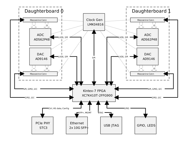
The x310 hardware can be fitted with one or two UBX160 daughter boards. The UBX160 contains hardware used to combine the separate baseband I and Q signals from the mother board and to modulate them to form the RF signal for transmission. The received carrier signal undergoes the reverse process. The block diagram of the UBX160 is shown below.
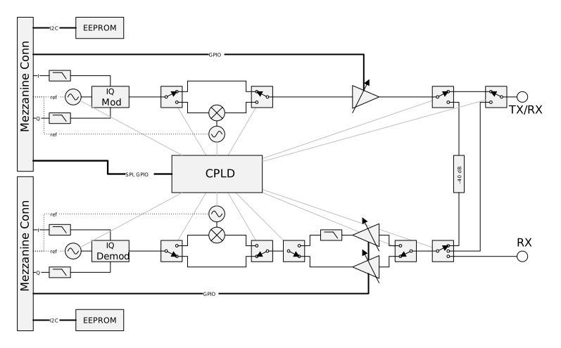
The drc_x310 supports both one and two UBX160 daughter board configurations The number of daughter boards present is set using the worker parameters
db0_is_present
db1_is_present
Setting the appropriate parameter to true informs the DRC that the specific daughter board has been fitted to the x310
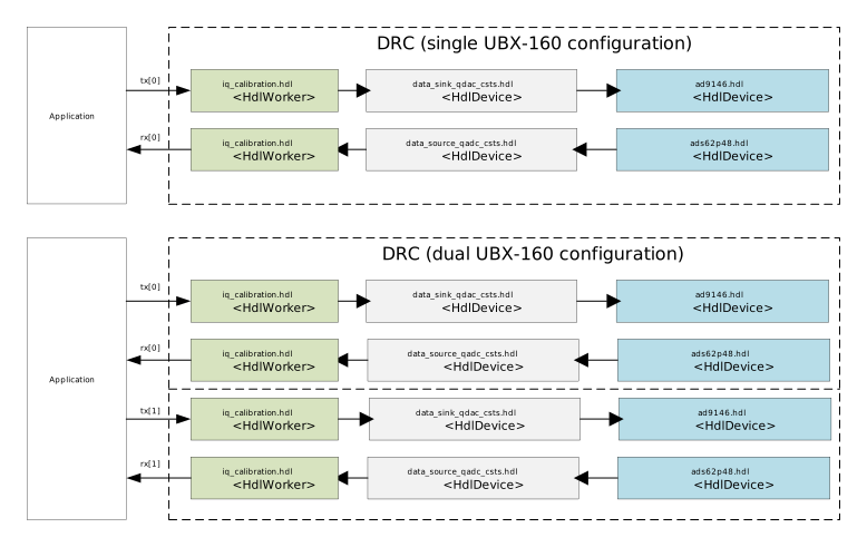
The DRC controls a number of slave device workers. It ensures that these slaves are started in the correct order. The clock generator (LMK04816) being started before the other devices. The (HDL) device workers controlled by the DRC, and their relationship to the hardware are shown in the diagram below
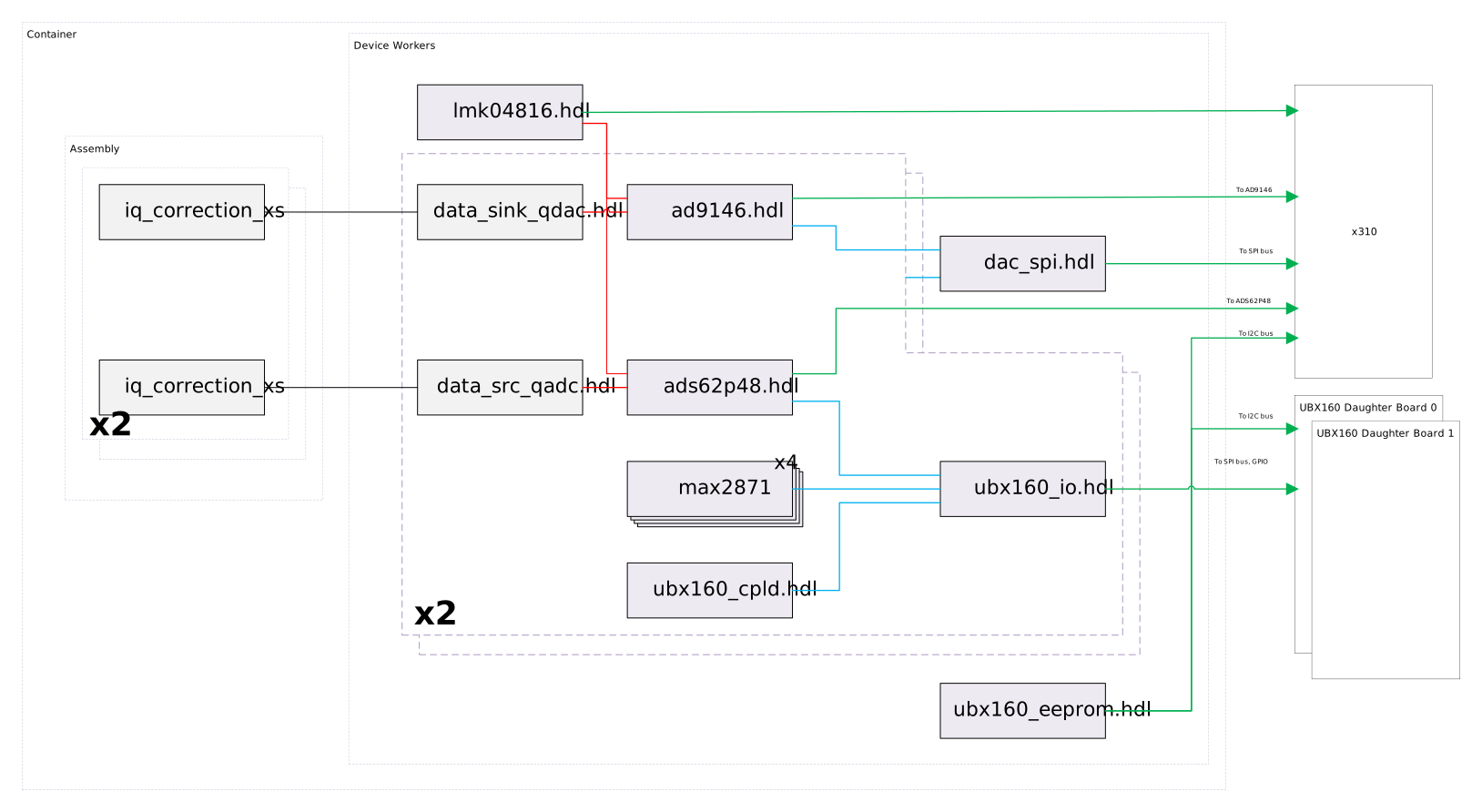
Each of the device workers has a corresponding class instance that is used to access the device worker properties. The drc_x310 classes, their relationship to the hdl device workers and to each other is shown in the diagram below
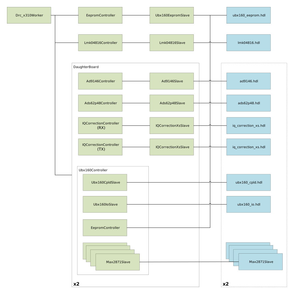
An application using the drc_x310 connects to one or more of the DRC’s ports. Connecting to these ports establishes data stream connections to the underlying DAC and ADC’s. The drc_x310 has an array of input ports. This port is named ‘tx’. tx[0] is connected to the daughter board 0 transmit path. tx[1] is connected to daughter board 1. Similarly, the drc_x310 has an array of output ports. rx[0] is connected to the daughter board 0 receive path. rx[1] is connected to daughter board 1 receive path.
The DRC provides a standardised set of properties that an application can use to configure
the radio hardware. Configuration is performed by setting the configurations property.
The configuration to use is chosen by writing the index of the configuration to the
start property (see OpenCPI Platform Development Guide for details on how to use a DRC).
The application code snippet below shows the use of the DRC configuration property (for a single UBX160 configuration)
Two channels are defined one for the transmit path (rx false) and one for the receive path (rx true).
The tuning_freq_Mhz property sets the carrier frequency. The sampling_rate_Msps 200.0 MHx property defines the sample rate.
The gain_dB property can be used to set the channel gain. Note these properties are defined for both the transmit
and receive channels.
The daughterboard is selected by examining the RF ports requested either by number (rf_port_num) or name (rf_port_name),
which are properties of the channel configuration. If (rf_port_name) is set then that will be used in preference to (rf_port_num).
The naming scheme follows the front panel, and is numbered as follows:
Name |
Number |
|---|---|
TX/RX_A |
0 |
RX2_A |
1 |
TX/RX_B |
2 |
RX2_B |
3 |
CAL_A |
4 |
CAL_B |
5 |
When using a dual UBX160 configuration four channels need to be defined.
<Instance Component='ocpi.platform.drc' worker='drc_x310' Name="drc">
    <Property name='db0_is_present' value='true' />
    <Property name='db1_is_present' value='false' />

    <Property name='configurations' value='{description myconfig, recoverable false, channels {
        {
          description TX_0,
          rx false,
          tuning_freq_Mhz 2400.0,
          bandwidth_3db_Mhz 1.0,
          sampling_rate_Msps 200.0,
          samples_are_complex true,
          gain_mode auto,
          gain_dB 30.0,
          tolerance_tuning_freq_mhz 0.01,
          tolerance_bandwidth_3dB_Mhz 0.01,
          tolerance_sampling_rate_msps 0.01,
          tolerance_gain_db 1,
          rf_port_name TX/RX_A,
          app_port_num 0
        },
        {
          description RX_0,
          rx true,
          tuning_freq_Mhz 2400.0,
          bandwidth_3db_Mhz 1.0,
          sampling_rate_Msps 200.0,
          samples_are_complex true,
          gain_mode auto,
          gain_dB 10.0,
          tolerance_tuning_freq_mhz 0.01,
          tolerance_bandwidth_3dB_Mhz 0.01,
          tolerance_sampling_rate_msps 0.01,
          tolerance_gain_db 1,
          rf_port_name RX2_A,
          app_port_num 0
        }}}' />
    <Property name='start'   value='0' />
  </Instance>
The DRC controls the following slave workers controlling devices on the x310 mother board
ocpi.osp.ettus.devices.lmk04816.hdl
ocpi.osp.ettus.devices.ad9146.hdl
ocpi.osp.ettus.devices.ads62p48.hdl
The DRC reads the contents of the eeproms present on the mother and daughter boards using the following slave worker
ocpi.osp.ettus.devices.ubx160_eeprom.hdl
The DRC also controls an instance of the following slave workers present for each of the supported daughter cards
ocpi.osp.ettus.devices.ubx160_io.hdl
ocpi.osp.ettus.devices.ubx160_cpld.hdl
ocpi.osp.ettus.devices.max2871.hdl (RXLO1)
ocpi.osp.ettus.devices.max2871.hdl (RXLO2)
ocpi.osp.ettus.devices.max2871.hdl (TXL01)
ocpi.osp.ettus.devices.max2871.hdl (TXL02)
The DRC uses the following slave workers to provide connections for streamed transmit and received data
ocpi.platform.devices.data_sink_qdac_csts.hdl
ocpi.platform.devices.data_src_qadc_csts.hdl
The DRC controls four IQ-Correction components. Two instances are used for each daughter board one for the transmit (TX) and one for the receive (RX) data directions. These components are instanced within the assembly (i.e. they are not device workers)
ocpi.osp.ettus.iq_correction_xs.hdl
lmk04816.hdl
The LMK04816 is a low noise clock generator fitted to the x310 mother board. It is used to generate the ADC, DAC and daughter board clocks. The DRC is responsible for the configuration of the clock generator. This is performed by the lmk040816_controller (.cc/.hh), this uses the slaves/lmk04816_slave.hh to read and write the properties of the lmk04816.hdl device worker. The lmk04816.hdl device worker provides access to the registers of the LMK04816 device via its SPI interface.
ad9146.hdl
The AD9146 is a dual 16-bit digital-to-analogue converter (DAC). There are two AD9146 devices on the x310 mother board. Each device generates the analogue I and Q baseband signals for a single daughter board. The DRC has two instances of the ad9146_controller (.hh/.cc), one for each daughter board. Each controller uses an instance of slaves/ad9146_slave.hh class to read and write the properties of the associated ad9146.hdl device worker. The ad9146.hdl device worker provides access to the registers of the AD9146 device via its SPI interface.
ads62p48.hdl
The ADS62P48 is a dual 14-bit analogue-to-digital converter (ADC). There are two ADS62P48 devices on the x310 mother board. Each devices digitises the analogue I and Q baseband signals from a single daughter board. The DRC has two instances of the ads62p48_controller (.hh/.cc), one for each daughter board. Each controller uses an instance of slaves/ads62p48.hh class to read and write the properties of the associated ads62p48.hdl device worker. The ads62p48.hdl device worker provides access to the registers of the ADS62P48 device via its SPI interface.
ubx160_io
The UBX160_io.hdl device worker provides the means to read and write a number of GPIO signals used to control a UBX160 daughter board. The device worker is controlled by the ubx160_controller (.hh/.cc). One controller instance is used for each daughter board present. The ubx160_controller uses an instance of the slaves/ubx160_io_slave (.hh) class to read and write the properties of the ubx160_io.hdl device worker. Note the ubx160_io.hdl device worker also contains the implementation of the SPI interface used by the AD9146, ADS62P48 and UBX160_CPLD devices.
ubx160_cpld
The ubx160_cpld.hdl device worker provides the means to control the CPLD device on the UBX160 daughter board. It is controlled by the ubx160_controller (.hh/.cc). One controller instance is used for each daughter board present. The ubx160_controller uses an instance of the slaves/ubx160_io_slave (.hh) class to read and write the properties of the ubx160_cpld.hdl device worker.
max2871.hdl
The MAX2871 is an ultra-wideband phase-locked loop (PLL) with integrated voltage control oscillators (VCOs). Each UBX160 daughter board has 4 MAX2871 devices. These are used for generating the transmit (TXLO1/TXLO2) and receiver (RXLO1/RXLO2) clocks. The four devices are controlled by the ubx160_controller (.hh/.cc). The controller has one instance of the slaves/max2871_slave(.hh) for each MAX2871 device. Each instance uses an instance of max2871.hdl device worker to gain access to the MAX2871 registers.
ubx160_eeprom.hdl
Each UBX160 daughter board has two I2C serial eeproms (Microchip 24LC024 2Kb I2C Serial EEPROM) containing the daughter board id, revision and serial number. In addition the x310 mother board itself also has its own serial eeprom (Microchip 24LC256 256Kb I2C Serial EEPROM). These eeproms are read using the eeprom_controller (.hh/.cc). This uses an instance of slaves/ubx160_eeprom_slave(.hh) which in turn accesses the ubx160_eeprom.hdl device worker to drive the I2C bus. The eeprom contents is read when the controller is started. The eeprom contents is cached by the controller.
data_sink_qdac_csts.hdl
An instance of this worker is used for each of the two transmit data streams (one for each daughter board). It is used to connect the transmit data stream to the DAC device.
data_src_qadc_csts.hdl
An instance of this worker is used for each of the two receive data streams (one for each daughter board). It is used to connect the ADC, producing data on the receive data stream.
iq_correction_xs.hdl
This component is used to provide DC level and I/Q balance correction in both transmit and received directions. For each of the two daughter boards. The calibration data for the I/Q correction components is frequency dependent. The values required by the component are read from files specified by the DRC (initial) properties
calib_path (default=./)
calib_db0_base (default=cal_v0.2_30FED7E)
calib_db1_base (default=cal_v0.2_30FED7E)
Hardware note
There are a number of revisions of the UBX160 daughterboard that the X310 platform uses. We have done our testing on the revision 5 / E boards. Earlier revisions, such as the revision 3 / C boards have issues with very low TX/RX -> RX2 isolation, as well as lacking an internal calibration loopback path. There is a separate note about this in the calibration application.
Worker Properties
db0_is_present: set this property to true when (UBX160) daughter board 0 is present.Type:
boolAccess:
Parameter:
TrueWritable:
FalseInitial:
FalseVolatile:
FalseRead back:
False
Default value:
None
db1_is_present: set this property to true when (UBX160) daughter board 1 is present.Type:
boolAccess:
Parameter:
TrueWritable:
FalseInitial:
FalseVolatile:
FalseRead back:
False
Default value:
None
calib_enable: set this property to true when DC and IQ calibration is to be read from calibration files.Type:
boolAccess:
Parameter:
TrueWritable:
FalseInitial:
FalseVolatile:
FalseRead back:
False
Default value:
None
report_data_lossType:
boolAccess:
Parameter:
FalseWritable:
TrueInitial:
FalseVolatile:
FalseRead back:
False
Default value:
true
calib_path: this property is used to define the path to the calibration files.Type:
stringAccess:
Parameter:
FalseWritable:
FalseInitial:
TrueVolatile:
FalseRead back:
False
Default value:
./
calib_db0_base: this property specifies the base filename of the daughter board 0 calibration files.Type:
stringAccess:
Parameter:
FalseWritable:
FalseInitial:
TrueVolatile:
FalseRead back:
False
Default value:
cal_v0.2_30FED7E
calib_db1_base: this property specifies the base filename of the daughter board 1 calibration files.Type:
stringAccess:
Parameter:
FalseWritable:
FalseInitial:
TrueVolatile:
FalseRead back:
False
Default value:
cal_v0.2_30FED7E
calib_manual: this property can be used to set the IQ correction components parameters directly (i.e. not read from calibration files). This is an array (0=daughter board 0 rx correction; 1=daughter board 0 tx correction; 2=daughter board 1 rx correction; 3=daughter board 1 tx correction).Type:
structSequence length:
4Members:
Enable:
data_type:
bool
I_dc:
data_type:
double
Q_dc:
data_type:
double
A:
data_type:
double
B:
data_type:
double
Access:
Parameter:
FalseWritable:
TrueInitial:
FalseVolatile:
FalseRead back:
False
Default value:
None
daughter_boardType:
structSequence length:
2Members:
sn:
data_type:
stringstringlength:
64
Access:
Parameter:
FalseWritable:
FalseInitial:
FalseVolatile:
FalseRead back:
False
Default value:
None
ocpi_buffer_size_rxType:
ushortAccess:
Parameter:
FalseWritable:
FalseInitial:
TrueVolatile:
FalseRead back:
False
Default value:
0
Worker Ports
tx: transmit data stream (array). Daughter board 0 is connected to index=0; Daughter board 1 is connected to index=1.Protocol:
NoneOptional:
True
rx: receive data stream (array). Daughter board 0 is connected to index=0; Daughter board 1 is connected to index=1.Protocol:
NoneOptional:
True
Inputs:
Outputs: