GPIO Test Application (app_test_gpio_properties)
Test and reference applications for Ettus USRP X310 front panel GPIOs.
Description
These applications test the GPIOs on the Ettus X310 Platform and provide references for their use. There are two applications in this folder corresponding to the two ways in which the X310 front panel GPIOs can be controlled: via ports or properties:
app_test_gpio_ports.xml
app_test_gpio_properties.cc (ACI application)
Each application assumes jumper cables between certain pairs of GPIOs, forming an external loopback. The required setup is described below. Each application tests the input and output functionality of each pin. For each pair of connect pins, one pin is configured to output whilst the other pin receives the value as an input.
Hardware Portability
This application can be run using the X310 platform. The (FPGA) bitstream used can be a single or dual UBX-160 daughter board configuration, and can use either dual or single ethernet interfaces. It has been tested using the loopback_assy assembly. This in turn uses the cfg_dual_ubx_160.xml configuration (i.e. dual daughter board / dual ethernet).
Execution
Prerequisites
The front panel GPIOs must be connected (with jumper leads) such that pairs of pins form an external loopback. Specifically, the following data pins must be connected:
D0 - D6
D1 - D7
D2 - D8
D3 - D9
D4 - D10
D5 - D11
This corresponds to the following diagram. Data pins 0-11 are physical pins 2-13 as per the Ettus documention. Pins 1, 14, 15 do not need to be connected: they are tied to +3.3V, GND, GND respectively.
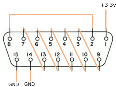
The container must be built such that the in, out and dir ports of the x310_gpio
device worker are connected to the CPU interconnect, bypassing the assembly. The loopback_assy
assembly provided with this OSP is appropriate. Other applications may, of course, choose to
connect the GPIO worker to the assembly instead for HDL, rather than RCC, control.
The x310_gpio device worker must be built with the parameter EVENT_MODE set to true.
This can be done in the appropriate platform configuration XML.
Command(s)
Follow the instructions in the X310 Getting Started Guide.
To run app_test_gpio_ports.xml:
$ cd opencpi/projects/osps/ocpi.osp.ettus/applications/app_test_gpio_properties
$ ocpirun -l 7 app_test_gpio_ports.xml
To run app_test_gpio_properties:
$ cd opencpi/projects/osps/ocpi.osp.ettus/applications/app_test_gpio_properties
$ ocpidev build
$ sudo setcap CAP_NET_RAW+eip target-centos7/app_test_gpio_properties
$ ocpidev run
Verification
In app_test_gpio_ports.xml each test will report some diagnostic information. If any
test fails the program will exit with an exception and a brief description of the expected
vs actual state.
In app_test_gpio_properties each test will either report Test passed or
Test failed along with a brief description of the expected vs actual state. If any
test fails the program will exit with code 1, otherwise it will exit with code 0.
Troubleshooting
These applications can not test the x310_gpio worker when its parameter EVENT_MODE is
set to false. This is because the data rate required to flow over DG-RDMA is too high.
This configuration is appropriate when the GPIOs interact with an HDL worker rather than an
RCC worker.
These applications do not test under other non-default parameter values of x310_gpio such
as USE_DEBOUNCE and EDGE_MODE.